Steel Design to Eurocode 3 (EC3)
In terms of structural engineering, Eurocodes are a relatively new development. These were introduced and first drafts published in the 1990s, and a full set of codes was finalised and published in 2000s. The structural code EN 1993-1-1: General rules and rules for buildings for the design of steel structures (CEN, 2005) was approved by the European Committee for Standardization (CEN) on 16 April 2004.
The condensed Eurocode 3 (Brettle & Brown, 2009) contains the very good and extensive design guidance provided in a readable form. The book is accompanied by two further publications containing worked examples for open and hollow sections to EC3 which were crucial in validating the code of the developed application: (Brettle & Brown, 2008) & (E & Brown, 2009).
Appendix A of the Concise EC3 contains design procedures for various design problems, which provide the basis of the sizing algorithm implemented within this application. These contain the basic sequence of sizing checks required to size steel beams in accordance with EC3 and help guide both engineers and developers of sizing tools. The code within the application which is detailed further in the following chapters closely follows these diagrams, and these are thus reproduced below:
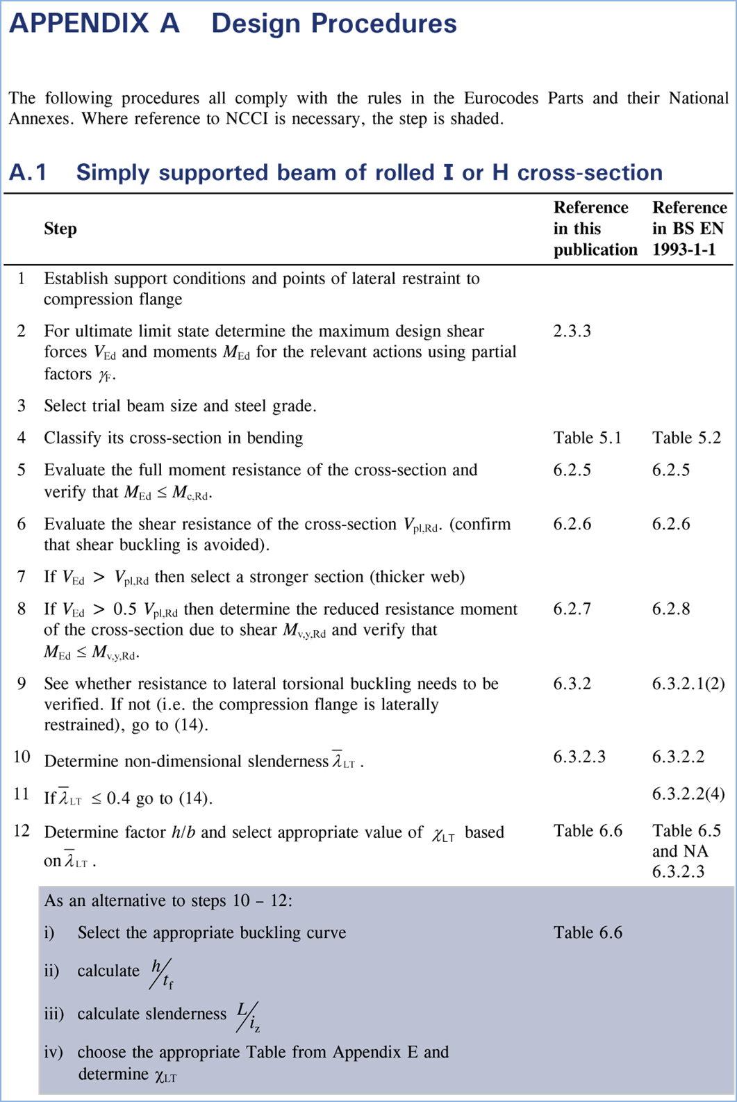
Figure 2‑1 Condensed EC3 Appendix A - Design Procedures (Brettle & Brown, 2009)
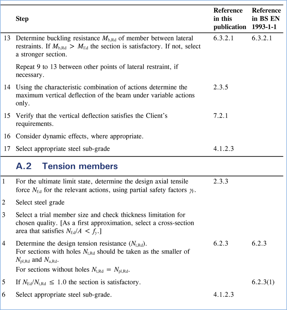
Figure 2‑2 Condensed EC3 Appendix A - Design Procedures (Brettle & Brown, 2009)
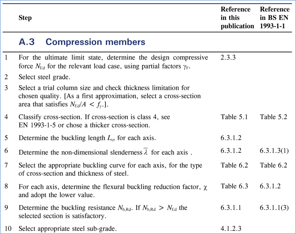
Figure 2‑3 Condensed EC3 Appendix A - Design Procedures (Brettle & Brown, 2009)
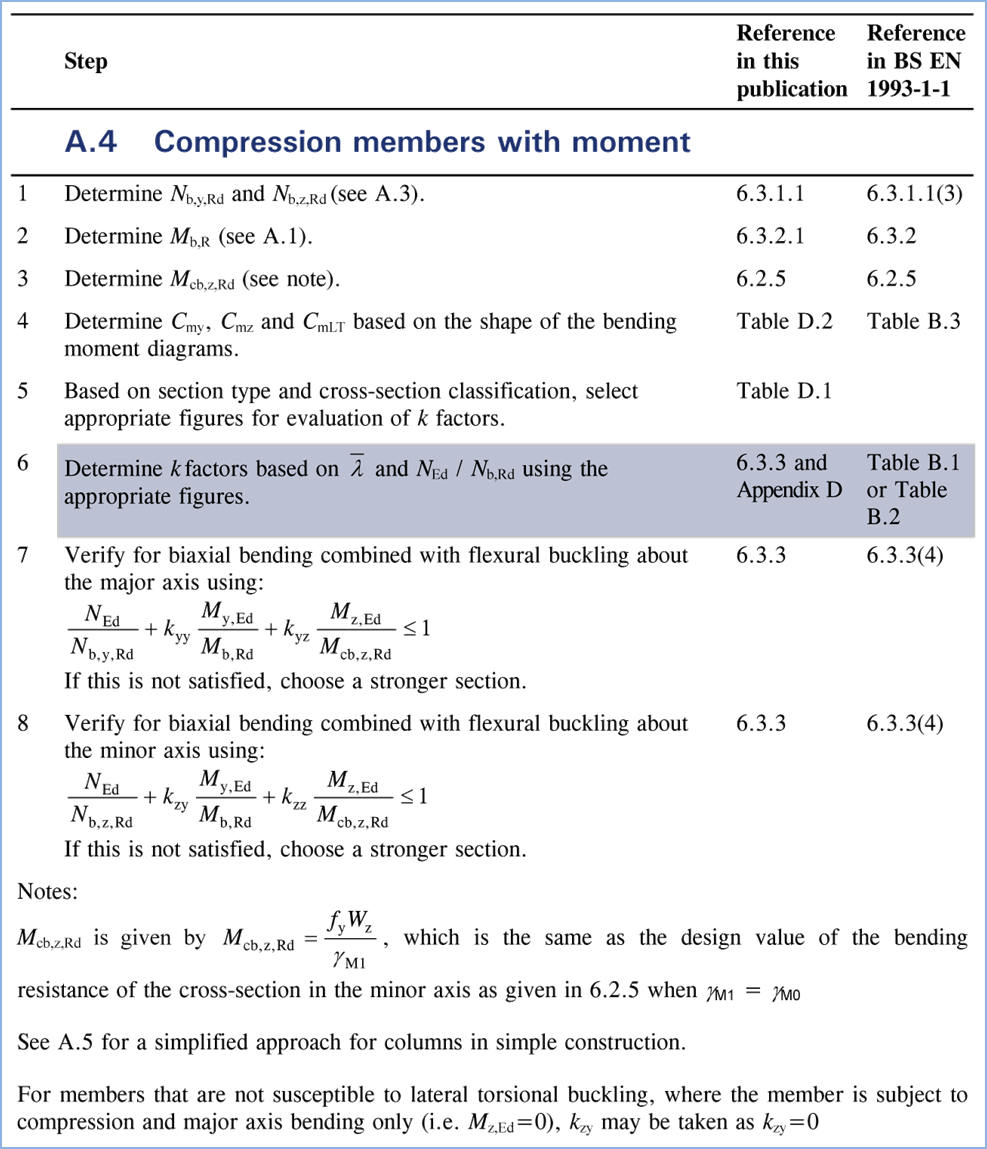
Figure 2‑4 Condensed EC3 Appendix A - Design Procedures (Brettle & Brown, 2009)
The application utilises these algorithms to perform steel sizing and also to verify Ultimate Limit State (ULS) capacity of sections as part of the optimisation procedure.
A publication (jointly published by the The Steel Construction Institute, Tata Steel & The British Constructional Steelwork Association Ltd., 2011) contains a wealth of additional information about various less frequently encountered problems within steel design not contained within the Concise Euro code or within the actual code. The publication covers issues such as torsional and torsional-flexural buckling of non doubly-symmetric sections which are only briefly mentioned within the concise eurocode and the code itself but were required for the development of the application which has a broad field of use.
Very little guidance for obtaining the Lateral Torsional Buckling Factors C1 & C2 is contained within the eurocode. These are very important in finding the LTB resistance of a member (Mcr). A such, a non-contradictory complementary information (NCCI) was published (Bureau & Galea, 2010) providing the additional guidance incl formulae and diagrams.
The application interpolates the values provided within the diagrams in figures 3.3 and 3.5 from the NCCI to find LTB factor C1. Figure 3.3 is reproduced below, whereas other diagrams can be found within the publication.
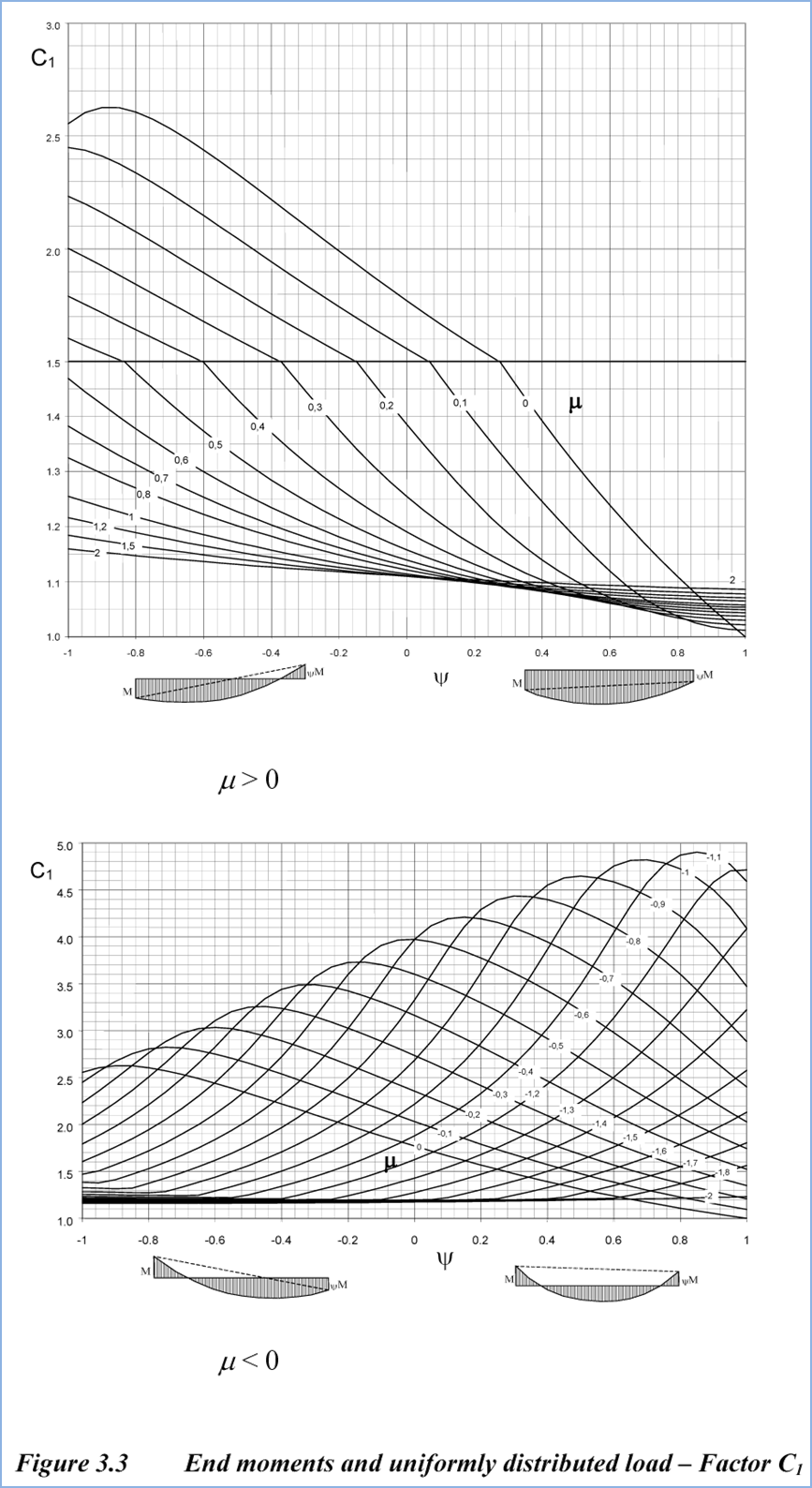
Figure 2‑5 Figure 3.3 showing the values of C1 reproduced from the NCCI (Bureau & Galea, 2010)
Finally, the blue book has always been the necessary tool used by steel designers. It contains numerical tabulated geometrical data about the available steel sections as well as the calculated bending moment capacity and lateral torsional moment resistance (based on length). The new interactive bluebook was recently updated in accordance with EC3 and is hosted and published by Tata Steel and available online (Tata Steel, n.d.). The published section geometry information was used within the tool.
Beam Sizing to EC3 – Implementation within konstrct.com
The sizing algorithm is based on the information contained within EC3 (CEN, 2005),The Concise Eurocode 3 (Brettle & Brown, 2009) and the associated Examples (Brettle, 2009), (Brettle & Brown, 2008). The concepts and the contents of these publications is presented above.
The actual implementation of the procedure is presented in a series of diagrams contained in the following pages. Note that the procedure is very complex and contains a large amount of checks. For simplicity some of the less commonly utilised checks have not been presented in the diagram. The reader is referred to the publications listed above and the actual code of the application.
As a brief overview, the procedure initially assembles the relevant factored, ultimate member forces for each element and reads the element properties. At this stage it also performs the initial capacity checks (eg P/Afy; M/Wel, etc) to quickly discard substantially undersized sections and save processing time. Using these checks the algorithm also determines which detailed checks are required to be carried out. If the applied axial force and bending moment are within 0.5 or 1% of the capacity, detailed checks will not be carried out to optimise the output and avoid displaying unnecessary checks. The procedure then checks shear capacity, axial capacity and bucking, bending moment and lateral torsional buckling and finally carries out combined bending moment and axial capacity checks (all if required).
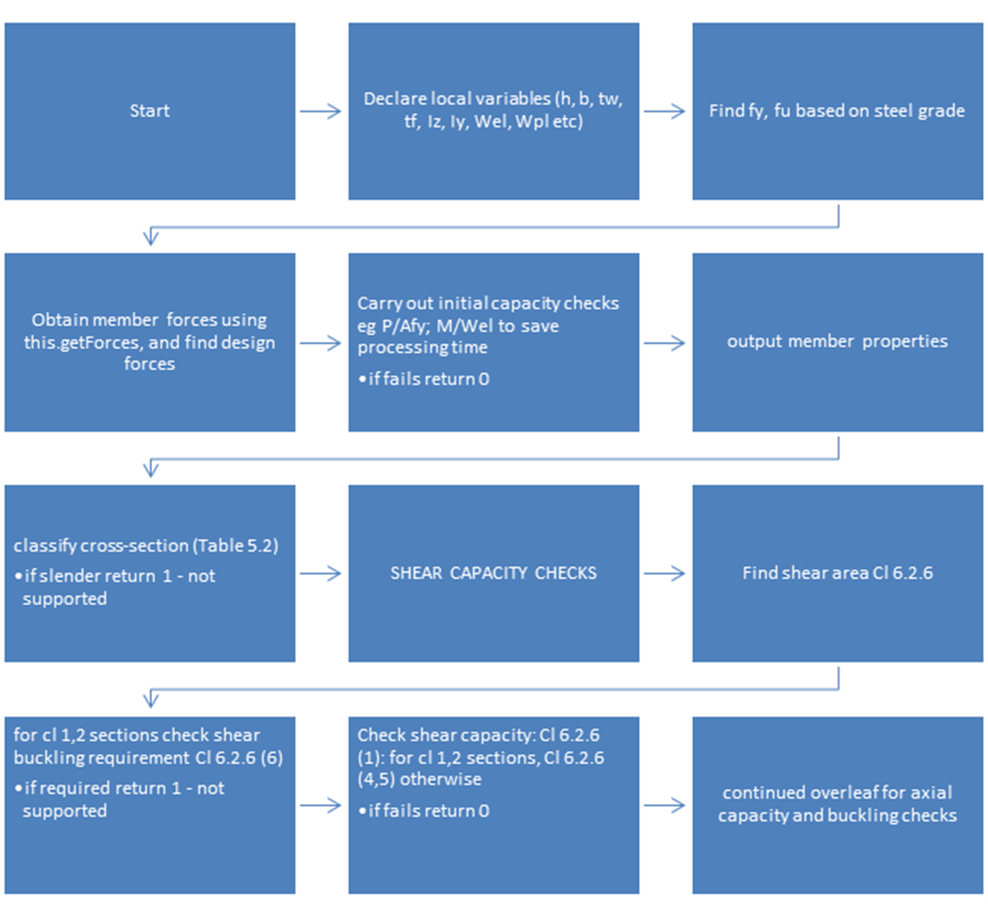
Figure 3‑2 Beam Sizing Algorithm Pt 1/4 – Input data, Classification, Shear Capacity (CEN, 2005)
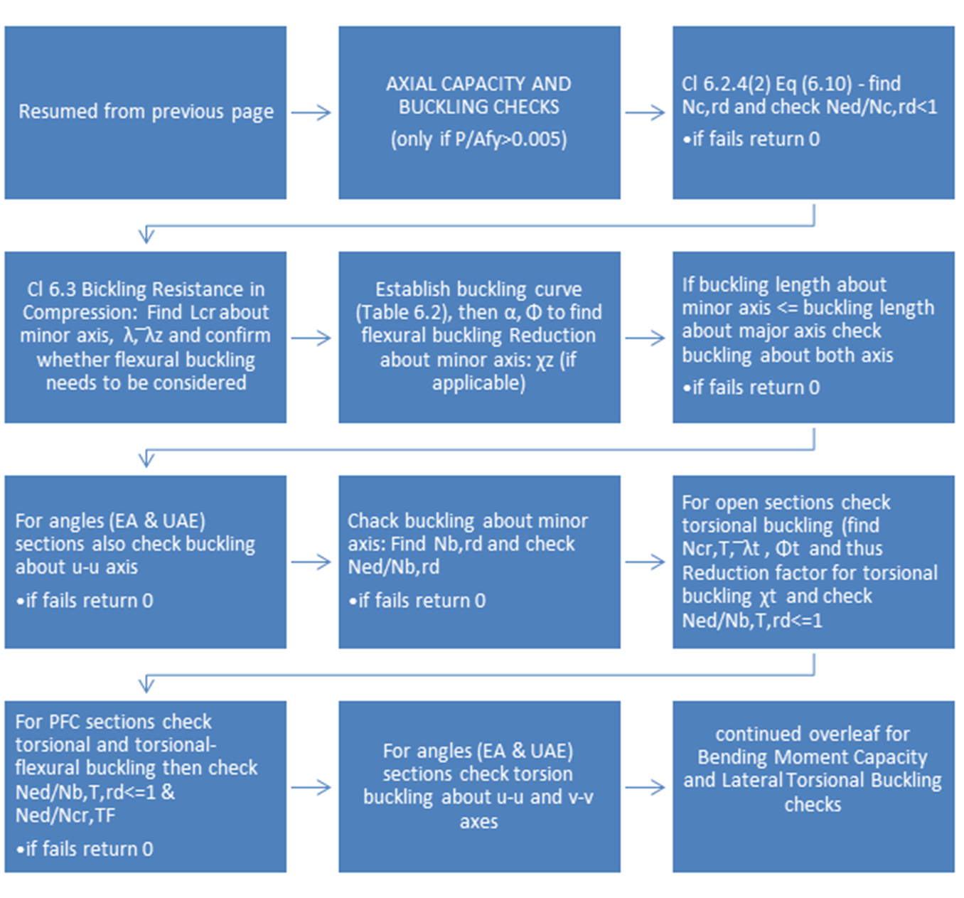
Figure 3‑3 Beam Sizing Algorithm Pt 2/4 – Axial Capacity and Buckling (CEN, 2005)
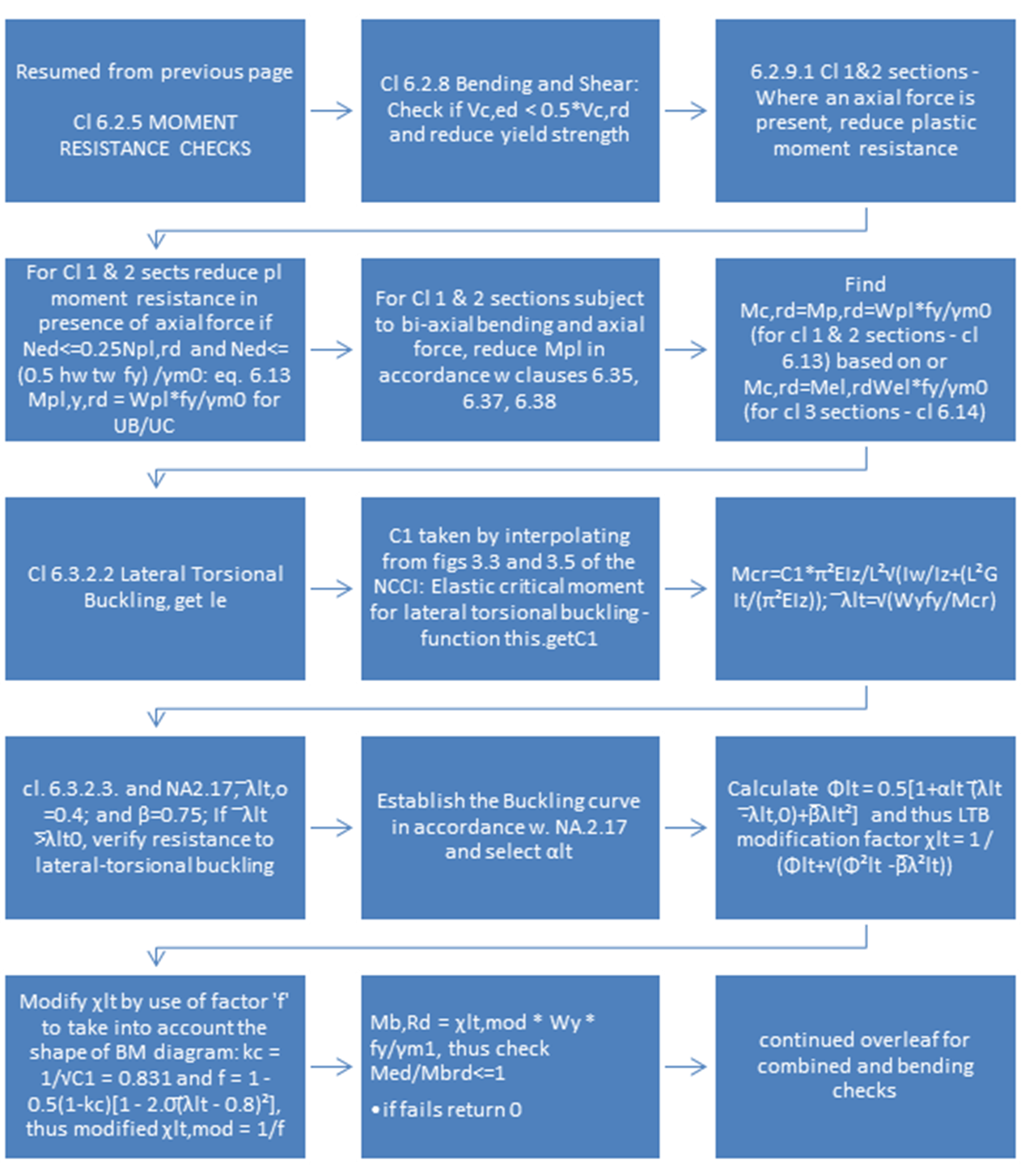
Figure 3‑4 Beam Sizing Algorithm Pt 3/4 – Bending Moment Capacity and Lateral Torsional (CEN, 2005)
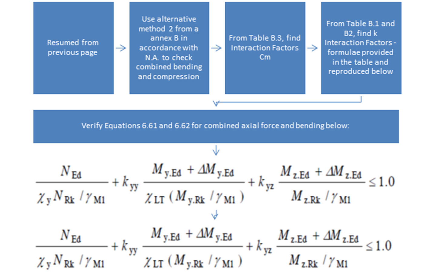
Figure 3‑5 Beam Sizing Algorithm Pt 4/4 – Combined axial and bending checks (CEN, 2005)
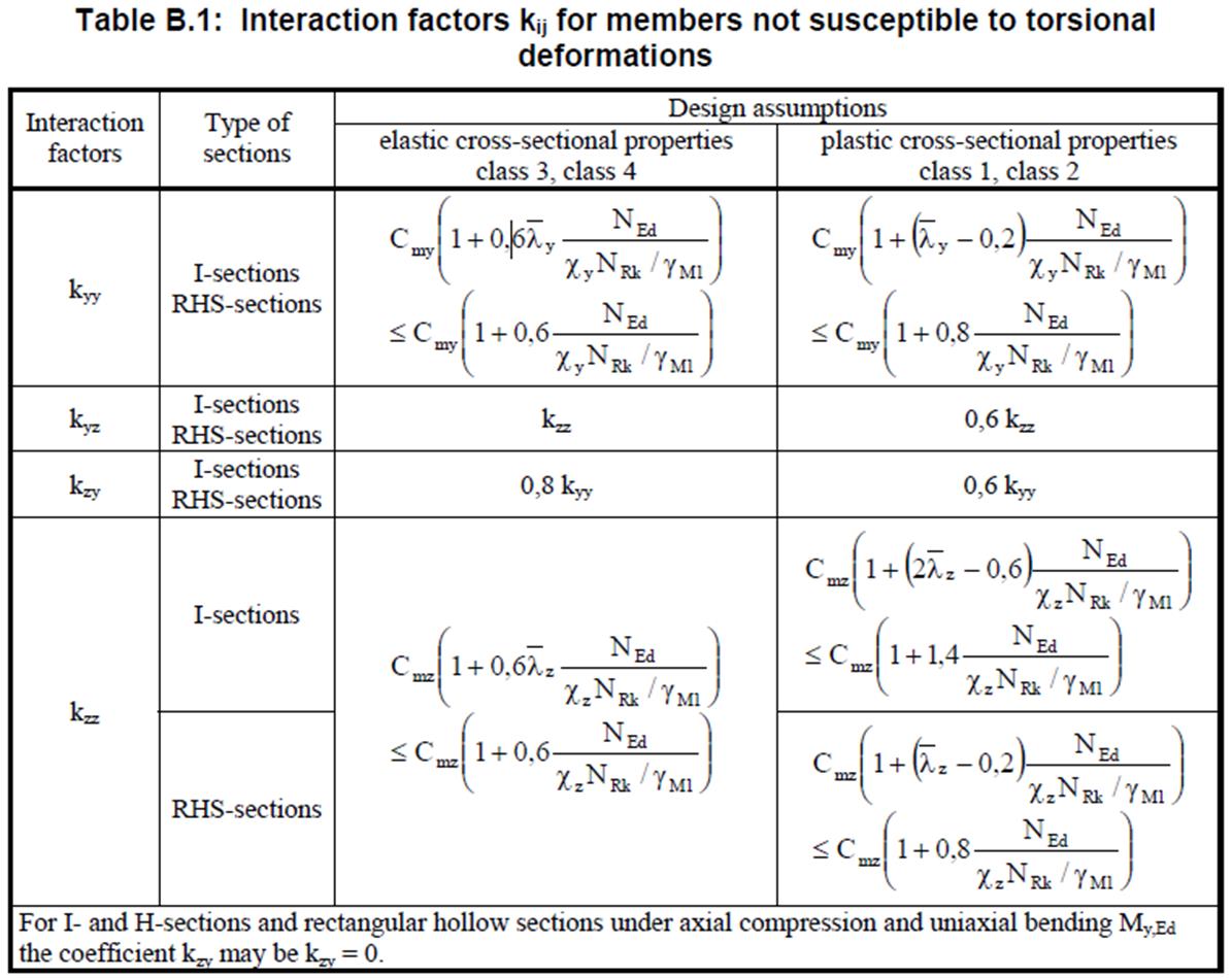
Figure 3‑6 - Interaction Factors kij (CEN, 2005)
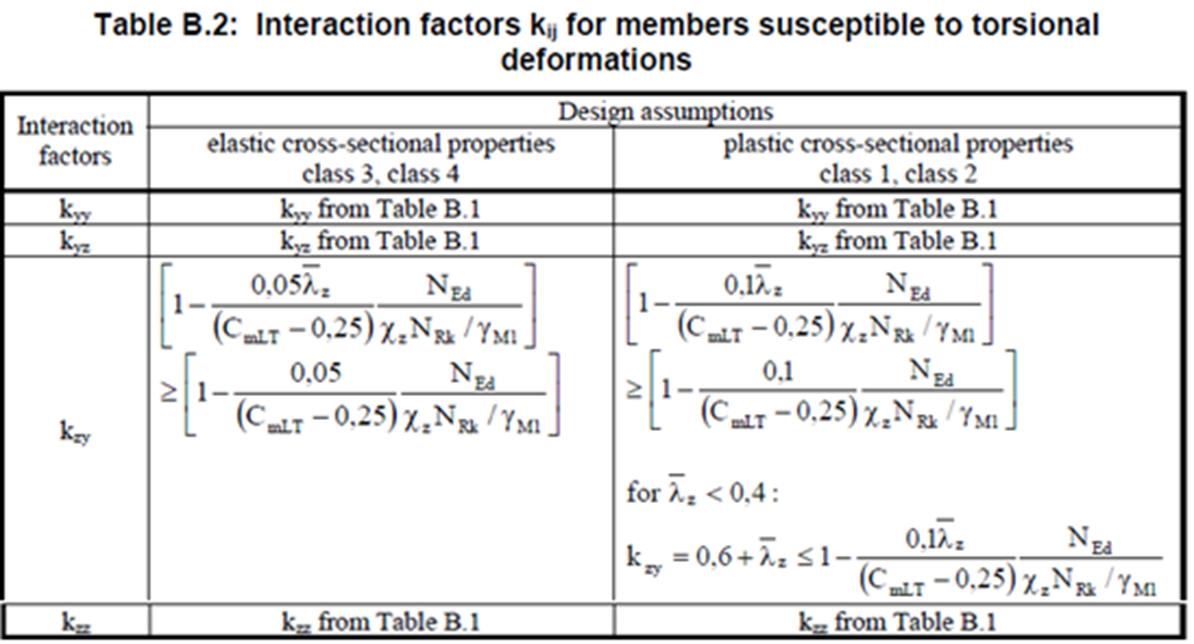
Figure 3‑7 – Interaction Factors kij (CEN, 2005)
Example beam calculations to EC3 reproduced from (Brettle, 2009)
In order to validate the steel sizing algorithm, a number of checks against the published example 12 within (Brettle, 2009) which provides worked examples for many typical sizing problems. Example 12 details of sizing for a major axis bending and compression of Class 3 section which fairly complex including buckling, lateral torsional buckling and a combined axial force and bending.
Several key sections from the publication have been reproduced below for comparison and also provides some graphical data:
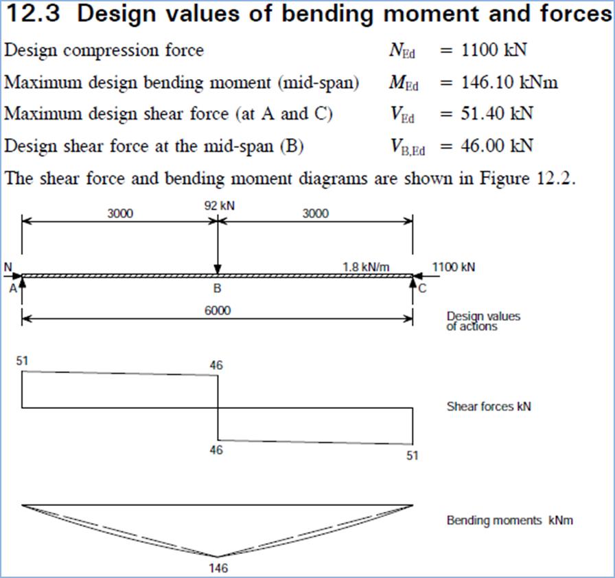
Figure 5‑17 – Steel Building Design, Worked Example 12, Sheet 2/14 - Design Forces (Brettle, 2009)
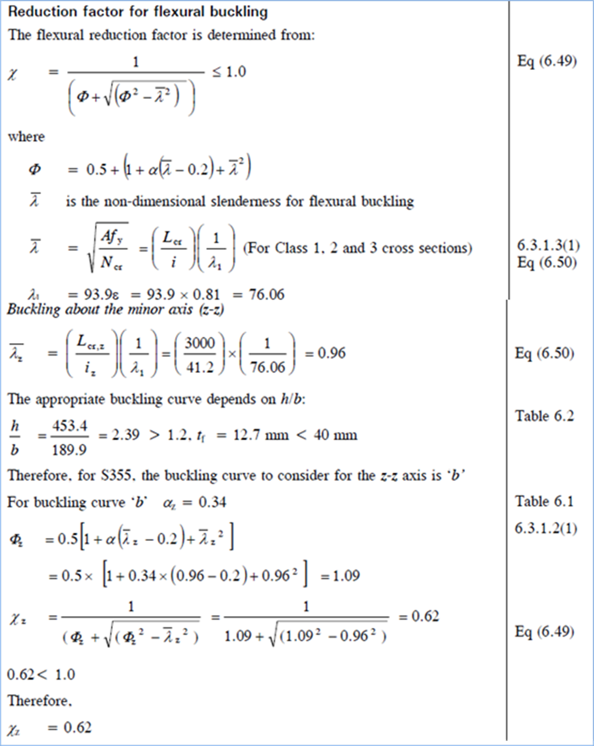
Figure 5‑18 Steel Building Design, Worked Example 12: Sheets 7&8/14 - Buckling about minor axis (Brettle, 2009)
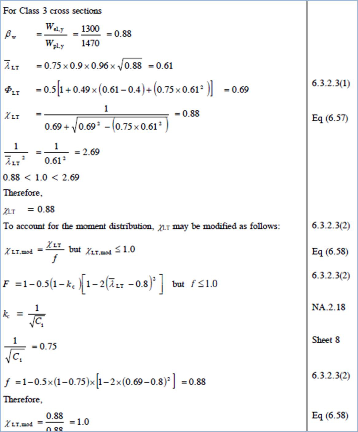
Figure 5‑19 Steel Building Design, Worked Example 12: Sheet 9/14, Lateral Torsional Buckling Reduction Factor (Brettle, 2009)
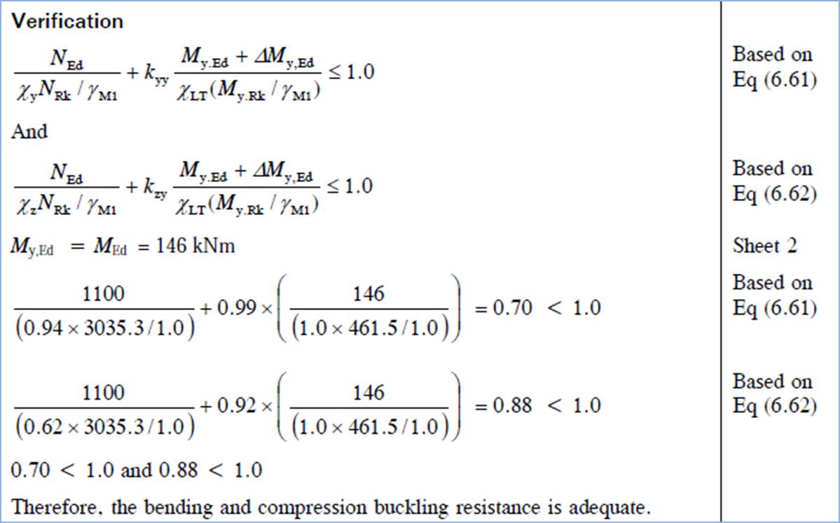
Figure 5‑20 Steel Building Design, Worked Example 12
- Sheet 11/14 - Final Verification (showing k factors) (Brettle, 2009)